The advantage of the Arduino architecture is that you can set up the development environment in no time. It probably takes you less than 10 minutes until the microcontroller (MC) finally blinks your first LED. This ease of use has made Arduino so popular among hobbyists. At some point, however, you wish to go beyond Arduino, produce standalone prototypes that may not require the USB connection nor the boot loader. You may also wish to tinker with the fuses that configure the MC at the hardware level and use clocks other than Arduino’s 16 MHz. In this project, we
- turn Arduino into an ISP (in-system programmer) that can program other Atmel MCs
- assemble a standalone setup of an ATmega 328P with an external 16Mhz crystal oscillator on a breadboard
- flash an Arduino program (sketch) onto this ATmega 328P
- change the fuse settings of the ATmega 328P
1. Development System
I work on a Linux computer (openSUSE 13.1, 64bit) and have the version arduino-1.0.5-linux64.tgz of the Arduino IDE installed with normal user privileges. My Arduino is an Arduino Uno R3.
I have not been able to use the avrdude tool that is included with Arduino in order to flash the fuse settings of the ATmega 328P. I therefore also use the vanilla avrdude, Version 5.11.1, that is included with openSUSE 13.1.
All breadboard diagrams have been drawn with Fritzing 0.9.0b which have I compiled from source.
Testing the Arduino
When I connect my Arduino to a powered USB connector at the computer, it appears as the character device /dev/ttyACM0. In order to access the Arduino when the Arduino IDE runs with normal user privileges, I need to
- either add the user to the group dialup (type
usermod -a -G dialout <username>as root) or make sure the device/dev/ttyACM0is user writable (chmod 777 /dev/ttyACM0as root). - make the directory
/var/lockuser writeable and executable (chmod 777 /var/lockas root).
I start the Arduino IDE by calling arduino in whatever directory I have installed it, and I make sure that the correct type of Arduino board is selected
Tools -> Board -> Arduino Uno
and that the correct serial interface is used
Tools -> Serial Port -> /dev/ttyACM0
I load the basic program (`sketch´) that blinks the LED
File -> Examples -> 01.Basic -> Blink
and compile it with
Sketch -> Verify/Compile
Now I can connect the Arduino to a powered USB connector at my computer, press the reset button on the Arduino and immediately select
File -> Upload
in order to have the Arduino boot loader transfer the program onto its flash memory. The LED at Arduino Pin 13 that is labelled `L´ on the Arduino Uno starts blinking. The Arduino is running the new program.
2. Turning the Arduino Uno into an In-System Programmer (ISP)
Now I load the program that turns Arduino into an ISP
File -> Examples -> ArduinoISP
compile it and upload it to the Arduino. Note that when a new window of the Arduino IDE has opened, you may have to set the board type and serial port again. Once the program ArduinoISP has been uploaded to the Arduino, the LED `L´ is always on as long as we have not yet connected anything to the Arduino that now performs as an ISP.
3. Standalone ATmega 328P
In the following, we refer to the pins of the standalone ATmega 328P by their original labels as shown in the data sheet (as opposed to the simplified Arduino terminology). This diagram is for the usual PDIP-28 package.

ATmega 328P with original pin labels (as opposed to Arduino conventions)
The minimal standalone ATmega 328P circuit with external crystal oscillator that worked for me is the one from the bottom right of the ArduinoISP Tutorial as shown here.
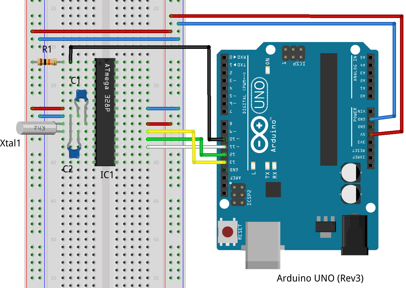
Standalone ATmega 328P with Arduino ISP
Here are the components.
| IC1 | Atmel ATmega 328P-PU |
| R1 | 10 kΩ |
| C1, C2 | 22 pF |
| Xtal1 | 16 MHz crystal |
The Arduino Uno will be powered by the computer through its USB connection. We then use the Arduino in order to power the breadboard (red and blue wires). The pins 7 (VCC) and 20 (AVCC) of the ATmega 328P are attached to 5V (VCC) on the Arduino while pins 8 (GND) and 22 (GND) are attached to ground (GND) on the Arduino. The 16 MHz crystal (Xtal1) sits between pin 9 (XTAL1) and 10 (XTAL2) of the ATmega 328P, and we have put one 22 pF capacitor each (C1 and C2) between ground and pin 9 and pin 10, respectively. The crystal with the two capacitors (plus some circuit inside the ATmega 328P) forms the external 16 MHz crystal oscillator that will provide the clock for our standalone ATmega 328P.
In order to program the ATmega 328P, the ISP needs to drive its pin 1 (^RESET, low active reset), pin 17 (MOSI, master-out-slave-in), pin 18 (MISO, master-in-slave-out) and pin 19 (SCK, system clock). We pull-up the reset pin 1 with the 10 kΩ resistor R1. This is basically an SPI interface in which the Arduino ISP is the Master, the standalone ATmega 328P the slave, and in which Slave Select is by pulling RESET low.
Note that in order to program an ATmega 328P with an ISP, it already needs a working clock signal because it has to communicate with the programmer. An ATmega 328P fresh from the factory usually has the fuse configuration set to run with its internal 1 MHz oscillator. In this case, no external circuit is required, and the external crystal oscillator on my breadboard is simply redundant.
Once the fuses of the ATmega 328P have been set to a different configuration, for example, to use an external 16 MHz crystal oscillator, the ATmega 328P works only when such an oscillator is present. Without it, there is no clock signal and it will simply not run and therefore cannot be programmed by an ISP either. Similarly, if the fuses have been set for an external clock signal, the MC will not run unless such a clock signal is present.
Whenever you set the fuses of an MC, it is therefore a good idea to keep a note of its clock settings so that you remember which kind of oscillator or clock signal it needs. Without the correct clock provided, you will not be able to use an ISP in order to change the fuses back.
4. Flashing an Arduino Sketch onto a Factory New ATmega 328P (Ooops)
Now that we have an Arduino ISP connected to a standalone and factory new ATmega 328P, let us see whether we can program it. Since the ATmega 328P is precisely the type of MC that is used in the Arduino Uno, we will be able to run Arduino programs without any change.
In the Arduino IDE, we go to the Blink program and make sure that the appropriate serial interface has been selected. In order to program a standalone ATmega 328P which `almost´ forms an Arduino Uno, we can select the board type
Tools -> Board -> Arduino Uno
As we are going to program it not using its Arduino boot loader (the factory new Atmega 328P simply does not have any), but with our Arduino ISP, we select
Tools -> Programmer -> Arduino as ISP
Then we write the Blink program to the standalone ATmega 328P by
File -> Upload Using Programmer
As soon as the programming has been completed, the standalone ATmega 328P starts running the blink program and keeps turning its pin 19 low and high and so on (which would be the Arduino pin 13 with the LED `L´ attached if it were inside an Arduino Uno). Right now, this pin 19 is still attached to pin 13 of the Arduino that we are using as the ISP. Therefore, our standalone ATmega 328P now blinks the LED `L´ of the Arduino ISP!
Remark. At first, you might think we have connected two outputs (pin 19 of the standalone ATmega 328P with pin 13 of the Arduino ISP which used to provide the system clock during the programming). This is usually a bad idea because if one output is low and the other one high, this short-circuits the drivers. Apparently, this is nevertheless safe in the present situation. I suppose the Arduino ISP has reconfigured pins 10 to 13 as inputs and removed the internal pull-up resistors as well as soon as the programming had completed. This way, the ISP is protected fom whatever goes on in the MC being programmed after programming has finished but before we have removed the connecting wires.
Good, we see that the LED `L´ on the Arduino is blinking. But it is doing so about 10 times slower than when the Blink program was running on the Arduino as opposed to the standalone ATmega 328P. The answer is the fuses. We have flashed the Blink program onto a factory new MC. Its fuse configuration is still the factory default, including running with the internal 1 MHz clock. Therefore the slow blinking.
Option 1. The Arduino Bootloader Sets the Fuses
In order to set the fuses of the standalone ATmega 328P to the Arduino standard configuration (it is the same MC, an ATmega 328P, after all), we can simply flash the Arduino boot loader onto the standalone ATmega 328P. In the Arduino IDE, we make sure that the serial port, board type and programmer are set to the same values as above when we flashed the Blink program to the standalone ATmega 328P with the Arduino ISP. Then we can flash the boot loader.
Tools -> Burn Bootloader
Once the boot loader has been written, the ATmega 328P resumes executing the Blink program which is still present, and the LED `L´ on the Arduino immediately starts blinking at the usual frequency. The boot loader has set the fuses to the Arduino values which includes being clocked by the external 16 MHz crystal oscillator.
Option 2. Setting the Fuses Manually.
Alternatively, we can do without the Arduino Boot Loader (our standalone ATmega 328P may end up in a household device and never again get connected to a PC – why would it need a boot loader?) and adjust the fuses directly. Apparently setting the fuses is a tricky issue, and so let us make sure we understand this as well.
For the fuses, we need the tool avrdude, but in the vanilla version that has nothing to do with Arduino. In our case, this is version 5.11.1 as contained in openSUSE 13.1. By typing which avrdude, we get /usr/bin/avrdude and can therefore confirm that by simply typing avrdude, we execute the vanilla version. The Arduino IDE contains a different, patched, version of avrdude, unfortunately under the same name. But that executable would be located somewhere in the directories of the Arduino IDE at <wherever>/arduino-1.0.5/hardware/tools/avrdude. I have not managed to set the fuses of the standalone ATmega 328P with the Arduino version of avrdude.
The standard Arduino fuse configuration for the ATmega 328P can be written to the standalone ATmega 328P by
avrdude -c stk500v1 -p m328p -P /dev/ttyACM0 -b 19200 -U lfuse:w:0xFF:m -U hfuse:w:0xDE:m -U efuse:w:0x05:m
Here the option -c specifies the type of programmer we use. For the Arduino ISP, we use stk500v1. The option -p gives the type of the Atmel microcontroller that we are programming. Here m328p stands for the Atmega 328P. The option -P specifies the serial device at which the Arduino ISP is connected, and -b is the baud rate at which we are communicating with the ISP. The three arguments with -U are finally the three bytes that encode the configuration of the fuses.
If you select a different baud rate (I had first tried the standard Arduino Uno baud rate of 115200), then avrdude will not even recognize the type of the chip that we are trying to set the fuses of and abort with
avrdude: Device signature = 0x000000

avrdude: Yikes! Invalid device signature.

Double check connections and try again, or use -F to override

this check.
Although the PC can talk to the Arduino ISP at the wrong baud rate and the ISP can even transmit data to the standalone ATmega 328P, the ISP is no longer able to receive data from the standalone. Instead, it seems to read only zero bytes and therefore cannot even confirm the type of micro-controller by its signature.
What made the troubleshooting difficult was the fact that the Arduino patched version of avrdude got the signature right and only produced errors later on when it finally verified the fuse settings. So I thought for quite some time that switching to the Arduino version of avrdude had gotten me closer to the solution. In fact it had not. The vanilla avrdude is the only one that works for my standalone setup.
In order to demonstrate that the fuse settings are effective, we can turn on the internal division of the clock by a factor of eight and flash the fuses as follows.
avrdude -c stk500v1 -p m328p -P /dev/ttyACM0 -b 19200 -U lfuse:w:0x7F:m -U hfuse:w:0xDE:m -U efuse:w:0x05:m
Immediately, the blinking of the LED `L´ on the Arduino Uno (which is still driven via the programming cable by the standalone ATmega 328P) is eight times slower. We have successfully set the fuses.
In order to understand which fuse configuration is encoded by which three bytes, you can consult the official ATmega 328P data sheet or simply use one of the online fuse calculators such as this fuse calculator.
Be warned that it is possible to set the fuses in such a way that the MC can never again be programmed by an ISP. In order to make sure you do not brick your MCs, remember that the option Serial program downloading (SPI) enabled is always ticked as well as that Reset Disabled (Enable PC6 as i/o pin) is never ticked. The ISP needs to pull the reset pin to ground in order to program the MC.
Remark. Even if your MC ends up in a fuse configuration in which it can no longer be programmed by an ISP, it is still possible to program it with a high voltage programmer. So strictly speaking it has not been bricked. These high voltage programmers are expensive though and if you brick less than perhaps some 50 to 100 MCs during your career, it should be cheaper without the high voltage programmer.
5. Removing the ISP
Once the standalone ATmega 328P has been flashed to our satisfaction, we can disconnect the Arduino ISP. In the following standalone circuit, we still use the Arduino Uno as a power source. We have also added an LED with a 560 Ω resistor R2 in order to be able to watch the blinking.

Standalone ATmega 328P with Arduino as a power source
Note that we have attached the LED between pin 19 and VCC, and so it lights up when the output pin is low. This is precisely inverse to the built-in LED of the Arduino Uno.
Finally, if you want to run the standalone ATmega 328P with any DC source between about 8.5V and 26.5V or with any AC source between about 6V and 18.5V effectively, the following shows a rather robust voltage regulator attached to the standalone ATmega 328P. It can power way more than just this one MC. Our Arduino is now free and available for other projects.
Here are the additional components.
| IC2 | LM 7805 |
| D1-D4 | 1N 5059 |
| D5 | 1N 4001 |
| C3 | 1000 μF |
| C4, C6 | 100 nF |
| C5 | 1 μF |
| R3 | 470 Ω |

Standalone ATmega 328P on a Breadboard with 7805 Voltage Regulator
The power source is attached to the screw terminal J1. The source can be AC or DC, and the polarity obviously does not matter. The rectifier is formed by the diodes D1 to D4. The input voltage is smoothed by C3 and C4 and then fed into the voltage regulator, an 7805 in a TO-220 package. The diagram shows the 7805 from its front side where the left one of the three pins is the input voltage and the right one the output voltage. Diode D5 protects the 7805 if some large capacity `behind´ it discharges once the power source has been disconnected. The output voltage is smoothed by C5 and C6 and used to power the existing part of the breadboard circuit. LED2 with R3 serves as a power indicator. Here is the schematics.
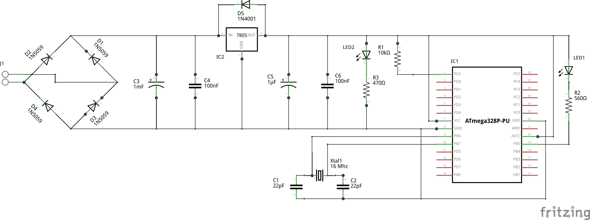
Standalone ATmega 328P-PU with Flexible AC/DC Power
6. Future Tasks
The next steps will be to change the fuses in such a way that there is no longer any flash memory reserved for the boot loader simply because a standalone programmed for a separate project will not require any. This should save us 1024 bytes of the 32768 bytes of flash memory. We may even want to compile C code for the MC outside the Arduino IDE, but still be able to use some Arduino libraries. Finally, a slightly modified procedure should allow us to program other standalone Atmel MCs. The ATtiny 44A-PU or the ATmega 1284P-PU would be interesting to understand.
I have posted the Fritzing files for the very last setup as well as a Fritzing part description for the ATmega 328P in which you see both the standard Atmel pin labels as well as the Arduino pin labels [in brackets] when you hoover the mouse over the pins.
I learned a lot about fuse programming from this posting by mogul at Let’s Make Robots.

Pingback: The Electric Henhouse | Park.
Hi
Thanks for wonderful tutorial.
I am able to upload the code to standalone atmega328p (using 1.0.5-r2) but not able to debug(on serial monitor).
Could you please let me know how can I do that.(I wrote sample program just to say ‘Hi’on serial monitor but it’s not showing any thing).
Thanks,
Som
LikeLike
Very good instructions,but how to set the fuses using arduino IDE? Or do you use avrdude as software for this job?
LikeLike
Pingback: Programación Arduino | Aprendiendo Arduino
Thanks for this post, the part about using an ISP to upload programs solved another problem I was having.
LikeLike
Good writeup. I think with this we can get rid on purchasing arduino board for every project
LikeLike
Thank You for this article !!!!
LikeLike
Great article!
The most comprehensive tutorial on how to program an ATMega328P using Arduino as a programmer. I have searched a lot and these instructions here were the clearest I could find. Worked like a charm from the first time I tried.
Thank you!
LikeLike
Hello
I have controller ATMEGA328 but without -PU at the end. Can i able to flash my controller using Arduino?
I tried but i could not flash it using Arduino.
Please suggest.
LikeLike
Pingback: Embedded Programming - ATMega32 AVR